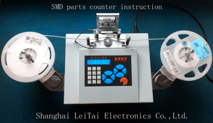
SMD parts counter instruction
Catalog
1. Function of counter, work environment and specification¡¡(one)
2. Function and operate instruction of the film panel¡¡¡¡¡.(two)
3. Operate method of the counter¡¡¡¡¡¡¡¡¡¡¡¡¡¡¡(three)
4. Matter needing attention for using¡¡¡¡¡¡¡¡¡¡¡¡¡¡(four)
5. Applied extension¡¡¡¡¡¡¡¡¡¡¡¡¡¡¡¡¡¡¡¡¡¡¡ (five)
Function:
1. Full-automatic electronic device counter with convenient, accurate and quick function which have promote heavily work efficiency and work equality based on artificial counter.
2. Adapting to ... provide workers with ...
3. Workers could set the distance between centers of two neighbor device according to mounts of devices to be counted.
4. The numbers of electronic devices date and company name (only English) could be printed out for next use.
£ª Work Environment
Work source: AC110V~220V50HZ
Power: about 15W
Numbers could be Counted: 1~100000 units
£ª Counter Specification
Shape Dimension: £¨L£©450 * £¨W£©270 * £¨H£©220mm
Weight: 9Kg
£ª Film Panel Function and Operating Instruction
€~¡ë-----character key: each key has not only the function of the number on it but also has the function of all characters under the number.
SPEED + ----- speed add key , This model do not have this feature
SPEED - ----- speed sub key , This model do not have this feature
PITCH-----pitch setting key: you can set the distance between two adjoining components on the
CLEAR-----delete key: delete the data on the current LCD screen. (notice: if under AUTO condition, number below COUNT will be deleted, if under MANL condition, number below SET will be deleted.)
LOSS----- loss function on/off key. If loss function is on condition,Machine can detect the empty part.And can miss out on the monitor displays the number of parts
MANL/AUTO----- MANL is the way of setting the number of components; AUTO is the way of counting the total number of components.
TIME-----time setting key: press it to enter into a state of time setting, then you can input year, month, day, hour, minute in turn. This input will be activated after pressing the ENTER key.
REWINDING-----motor rewinding key: the motor will redwing by pressing it.
STOP-----stop key: press it to stop counting.
START-----motor winding key: the motor will wind by pressing it.
£ª Operating Method
- LCD screen will display the data such as COUNT, PITCH, and SET etc after the counter connects to AC220V electrical source.
- Select well parameters of PITCH based on¡
- Fix electronic components to be counted on left¡shelf, meantime fix empty¡on right shelf.
- ¡¡the first 10-30 cm¡¡¡¡.direct at red arrow¡¡¡¡..divided
- if counter is under AUTO condition (here there is no information below SET on screen ), you can press START to start counting;
Once counting is completed, you can press PRINTER key, code printer will print out the correct¡
- If under AUTO condition (here 00000 condition will display below on the screen), before starts counting, please setting the number of components to be counted.
Repeat the 4th step
To start counting by pressing START key, when counting number exceeds the setting number, counter will stop (but because of inertia ¡will stop after the motor stops).
If because of inertia the number of components exceeds, you can manually rotate ¡counter cockily to needed number.
Notice
- Keep counter surface clean, away from humidly and high-temperature places.
- Take care when moving counter , place counter in where is smooth, clean.
- When equip ...,workers should ...for fear...and check ...
- When using counter, workers should check whether
- Under the MANL condition, counter will stop once giving number has been counted, the number will always adding on previous number when counter start working again.
- If worker press STOP key when counting, the screen will display the devices¡¯ number had be counted, here, if only press START key or REWINDING key to ... ,counter will continue counting.
- If ...when counting, here, workers should press stop key to stop counting firstly and fix ...secondly ,then press start key to continue.
- Eliminate electrostatic without fail when counter works, that is ,connect FG hole with grounded equipment.
- Cut off electrical source in time once counter is no need.
Applied extension
Resistance capacitance, IC and so on
Width: 65£¨MAX£©
Diameter 400£¨MAX£©
Space between¡.: 2£¬4£¬8£¬12£¬16£¬20£¬24£¬28£¬32£¬36£¬40£¬44£¬48£¬52£¬56
Unit is mm. |

